


Features
 Flight Mode Control
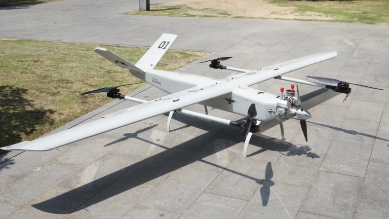
Support The Fixed Wing Vertical Takeoff And Landing : Greatly Reduce Dependence On The Site, Ejection Rack, Parachute, Etc., And The Operating Site Is Wide Adapted.Dual-Redundancy GNSS Positioning.
Flight Mode Control
Support The Fixed Wing Vertical Takeoff And Landing : Greatly Reduce Dependence On The Site, Ejection Rack, Parachute, Etc., And The Operating Site Is Wide Adapted.Dual-Redundancy GNSS Positioning. Video Camera Control
Support Real-Time Monitor Height And Distance,GPS Star Number, Flight Status Real-Time Dispay.Real-Time Display Flying Height, Distance, Heading Angle.Support The Fist View Monitoring.
Video Camera Control
Support Real-Time Monitor Height And Distance,GPS Star Number, Flight Status Real-Time Dispay.Real-Time Display Flying Height, Distance, Heading Angle.Support The Fist View Monitoring. One Key Return
Out Of Control Return, Flight Direction Lock, Law Battery Alarm And Data Recorder.Manual Stability, Autonomous Take-Off/Landing,Flying Attitude Stability/GPS Attitude Stability.
One Key Return
Out Of Control Return, Flight Direction Lock, Law Battery Alarm And Data Recorder.Manual Stability, Autonomous Take-Off/Landing,Flying Attitude Stability/GPS Attitude Stability. Waypoint Route Planning
Built-In Black Box Data Recording Function, Can Be Recorded About 60 Minutes Of Flight Data. Support For Connecting External Data Loggers, Record Up To 2000 Hours Of Flight Data.
Waypoint Route Planning
Built-In Black Box Data Recording Function, Can Be Recorded About 60 Minutes Of Flight Data. Support For Connecting External Data Loggers, Record Up To 2000 Hours Of Flight Data.


